Monday

11/27/2016

11/27/2016

Members Attending: Nick

The remote was assembled.  The ultrasonic sensors were tested in conjunction with each other without the previously stated problems.  Final assembly of the prototype was continued.  Now all sensor's were in their appropriate housing with wiring attached.

The remote almost fully assembled

11/21/2016

11/26/2016

Attending Members:  All

During this meeting we debugged and tested the control of the sensors.  We also tested five sensors together and tried to get them to run simultaneously.  We had issues doing this because of the way the code had been written.  The code caused the one sensor to run and then delay all vibrating motors and additional sensors until that vibrating motor's cycle was complete.

Thursday

11/17/2016

11/17/2016

Attending Members: Trung, Nick, Shane

We made edits to the final report.  We attempted to use a new multiplexer to control the motors.  The tests were unsuccessful. Additionally, the multiplexer was damaged in testing.  One of the pins(power in) was bent and ultimately snapped off.  The damage was not due to the circuit or stress, but human error.  We continued to test the circuit by using an additional wire to connect the multiplexer to the circuit.  The circuit seems to work with this modification erratically.

The team made an observation during our tests that the haptic motors began to emit low levels of heat after extended periods of testing.  Looking forward we may need to adjust the amount of current to the motors.

11/16/2016

11/16/2016

Members Attending: Trung, Nich


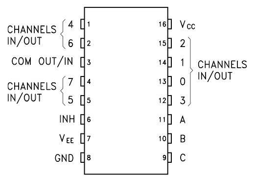
We have a meeting with Marco Janko to learn more about how to control multiple motors. He gave us a Multiplexer.

Outcome: We was able to control 2 motors at the same time using the multiplexer


Multiplexer 4051


Pin Map

Monday

11/14/2016

11/14/2016

Members Attending: All

The group worked on outlining the final presentation.  We continued troubleshooting our code for the Arduino.  We experienced issues with out multiplexer and using it to control the sensors and haptic motor.  Additionally, we assembled more of the components on the prototype.  Now the prototype has all five sensors and corresponding wiring.  The haptic motors have been placed but not permanently attached.  We plan to do so in the immediate future.

Side View of Prototype
Front View of Prototype
Top View of Prototype


11/12/2016

11/12/2016

Attending Members: Trung, Shane

During this meeting we discussed how to structure the code.  Specifically we focused on the demuxer and how it relays information that is received from the sensors to the motors.  During this meeting the team also researched how to import data from the Arduino to an excel sheet in order to test for accuracy.  We found a program that is available for free called "PLX_DAQ"  which we hope will use the serial output function of the Arduino program to gather data.


Saturday

11/5/2016


Re-enforced Sonic Sensors
11/5/2016

Attending Members: Anthony, Pietro, Trung, Nick, Shane

This meeting we began to assemble our prototype, and create our final report.

Nick brought the components to assemble the circuitry.  So of the more delicate components he reinforced with heat shrink to protect them form breaking under normal conditions.  He also soldered permanent wires on the haptic sensors, and sonic sensors.

Re-enforced Haptic Sensors
 We discussed adding a 6th sonic sensor and vibrating senor combination to the remote we have included to house the buttons to control the prototype.  This would allow the user to have a sensor in addition to the hat that they could use to navigate their enviroment in way that the sensors on the hat cannot or in any situation they choose.

Pietro began to assemble the prototype by sowing on the Sonic sensors to the hat.  The front most sensor will be added later using Velcro and large clips.

Our team discussed the placement of the haptic sensors and the feed back that the placement will give the user.  Our concern is that if the haptic motors are not mounted properly the user will feel feedback along the wires connecting them.  This could lead to a over stimulation and cause the user to not be able to feel meaningful feedback from the system.  We discussed the possibility of using this feedback along the wires to  make a 360 degree "variable" feedback between sensors so the user could, in theory, track an object as they move around the environment.  However, as a group we concluded that the feedback would not be useful to the user and might undermine the project by overstimulating the users senses.

Additionally, Nick and Trung made adjustments to the code used to run the haptic sensors and give feedback to the user.

Up close view of sown-in sensor
Side view of added Sonic Sensors
Front view of added Sonic Sensors without front sensor

Monday

10/31/2016


10/31/2016

Member Attendance:  Pietro, Anthony, Trung, Nick, Shane, Zach

This meeting we discussed how we are going to specifically mount the the sonic sensors up to the hat. Some problems were raised though. The geometry of the cap proved to be difficult to work with the sonic sensors. When we tried different positions on how users might want to wear the hat and concluded that there was too much lee way on how the sensors can be mounted at different angles. To remedy this we decided to place something rigid in between the hat and each sensor to keep them in place.

Below is our new circuit design. The 3 top sonic sensors will be mounted to the front of the hat and the 2 at the bottom will be mounted at the back. The power buttons to the right control the whole device, the front sensors, and the back senors from top to bottom. All of the sonic sensors are connected to the Arduino board which is connected to a board with all the haptic sensors (in the middle) controlling all the vibrations.

This is the new circuit design for S.A.V.E.

10/29/2016


10/29/2016

Attending Members: Nick, Trung, Shane, Pietro

During this meeting Shane edited this blog to reflect a new format. 

Nick and Trung worked to make a stable circuit.  Once assembled we tested the single sensor circuit with haptic motor.  The circuit  worked as designed by vibrating the haptic senor more intensely with an object closer, and vibrating less intensely for a farther away object.  The minimum distance that we applied to the sensor's programing was .5 meter and farthest 1 meter.  That being that if an object was one meter away from the user the haptic sensors would begin to vibrate softly, and as the object became closer to the user (up to .5m) the device the vibrations from the haptic motors become more intense.

Additionally, we tested using the Arduino in conjunction with an external power bank.  This is to make the device portable.  the Arduino will have the program for the device loaded on to it initially, and will only need a power source to run the sensor and hatpic motors.  The test was successful.  The Arduino, single sonic sensors, and haptic sensor ran.

One issue that was diagnosed was from this testing was the wiring for the haptic sensors is too weak.  The wire directly attached to the haptic motor broke from being moved repeatedly, due to intense vibrating.  Moving forward we plan to re-enforce the wire by soldering it to a longer wire to restrict movement and heat wrapping the connection to ensure lack of fraying.

Trung and Nick also began to work on expanding the programming of the Arduino to enable multiple sensors in conjunction with multiple haptic sensors.

The single sonic sensor
 circuit with single haptic
 motor and off/on switch
The same circuit as above 
with the external power bank 
supplying the Arduino and circuit

Haptic sensor that
 failed during testing


10/24/2016

10/24/2016

Member Attendance:  Pietro, Anthony, Trung, Nick, Shane, Zach

The lab period was spent on the continuation of designing the circuits and testing the limit on how far a user would want to know what's in his/her vicinity. This was more of a usability issue rather than technical or physical. The idea behind it is simply a user may not want to know everything within his/her arm-span which could cause the device to do more harm than good. However the
argument against it was that if the user didn't know an object that was immediately in front of him and ran into it, it'd  be an issue. To remedy this we decided on raising the range starting from 15cm.

We also now have a 3D model of the cap
An overhead of the 3D model of the cap w/o the sensors.
 Front View
Side View 
Rear View

Saturday

10/18/2016

10/18/2016

Member Attending: Nick

Assembly and testing of individual components.


Figure1.  Initial construction of the haptic driver motor with the vibration motor. Subsequent construction will consist of heavier gauged wire as the supplied wires from the manufacturer are insufficient to handle the force of vibration and in testing the wires have broken off at the solder joints

Figure 2. Initial testing of the haptic driver/vibration motor functions the DRV-2605L driver motor allows for 116 preset waveforms 4 of which are displayed here. 

Figure 3. Testing of multiple driver motors/vibration motors simultaneously with minimal delay between waveforms  

Figure 4. Initial integration testing with the HC-SR04 ultrasonic distance sensor and haptic driver unit. Waveform delay set to 2000ms at distances greater than 50cm and 200ms if less than 50cm. Subsequent coding will be based on a linear function where the delay will increase as distance increases.

Tuesday

10/16/2016

10/16/2016

Attending Members: Pietro, Anthony


The rough draft of the housing design for the sonic sensors and haptic motors
S.A.V.E. Design Project
This hat will be the "frame" for the final prototype
We decided on having every sensor sewed in with cloth made out of polyester and cotton for the comfort of the user. The cap is divided into 3 parts: the visor, the panels, and the strap. With that in mind we decided on having a cap with a relatively low visor so the sensors could pick up foreign objects within a 2-3 m radius from the user's feet. The first sensor will be directly in the middle of the visor and the visor will be offset at a -15° from the horizontal axis. The horizontal axis we chose was the user's forehead/peak point of the visor so the calculations and the visualization would be easier. Usually a cap would be in the range of -5 to -10° but that would be to far for the purposes of our design and might disturb the user with vibrations of objects more than 5m away.


This clip located on the front brim will house the front most sensor of our protoype
The sensors will be placed at a sufficient distance away from each other so that they don't interfere with one another. One sensor will be placed in the middle of the visor as the diagram shows. Two others will be placed at the end of the visors to ensure the user can know what is front of him/her. The last two will be placed at the ends of the strap for so the user can react to objects approaching his/her rear.


Sunday

10/15/2016

10/15/2016

Attending Members: Nick, Trung, Shane

Nick received the parts that we needed for the most(if not all) of the components we need for the sonic sensors, haptic vibrating motor, and Arduino. Trung and Nick have begun to program and assemble the Arduino, and sonic sensor.  Shane researched the haptic motors and how they are used. 
Trung and Nick assembling a basic circuit to test an led screen with Arduino for the purpose of testing the sonic sensor
 
This is the LED screen, Arduino, and a disconnected sonic sensor being assembled.

This is the same circuit as above.  Notice the screen is unreadable.
We ran into a problem setting up the testing LED screen.  We had to adjust the amount of voltage it was receiving because the voltage going to it was too much.  This made the screen display very bright and would not allow us to read the data being out put once we assembled the sonic sensor circuit. 

A similar circuit using Arduino and a sonic sensor
With this in mind, we continued the design of the circuits and researched different circuits that had been used for similar applications in the past. (Pictured right)

During this research we realized that by adding a variable resistor know we could more easily adjust he brightness of the LED screen and solve that issue.  Afterward including this in the circuit we were able to read the testing LED screen.

This is the Arduino with the new circuit and testing display LCD screen now functional

 Additionally, the team researched using a GoPro for Photogrammetry in order to verify our sensor's distance measurements.  This seems like it may be a good way to present and record data for our project.  However, the programming and computation required may present an issue.

Saturday

10/3/2016

10/3/2016

Attending Members: Pietro, Anthony, Trung, Nick, Shane, Zach

The group met and presented our proposal to the instructor.  We received feedback that we should split into subgroups to focus on housing design, system coding, and data recovery.  We all agreed to meet next Tuesday(11th) to have a collaborative meeting, and to show progress that each sub group makes.  We discussed the roles and responsibilities of each sub group.  The sub groups were decided to be as follows:

Design and building of the head piece mount (Pietro & Anthony)

Design and creation of the circuity and programming (Trung & Nick)

Testing and recording data (Shane & Zach)

We then divided into the sub groups to discuss what the appropriate next step would be for each piece of the project.  

Monday

10/1/16 Second Meeting

10/1/16

Attending Members: Nick, Trung, Shane, and Pietro

Our group met to further discuss the design project.  Our main effort for the meeting was to outline topics for the proposal.  We made significant progress as shown by the pictures below.

The group also discussed the Arduino modulation and programming.  Trung has previous experience with sonic sensors and Adruino which was instrumental in our thought process and design.

During this meeting we also choose to make our design wearable.  Specifically on someones head with possibly a small back pack to house a power supply and circuity.  We started to conceptualize the sensor, how many we would need, and their layout.

Nick purchased some materials from Amazon to start project.  What he order were the sonic sensors[INSERT EXACT SENSOR NAME HERE] and an Arduino kit.

As a group we decided it would be in our best interest to meet at least twice a week once in class, once outside of class.

Brain-storming of how we think the 
sensor circuit should behave with the Arduino
This is how we decided to divide the various
 tasks that we believe the project will require

First Meeting

9/30/16

Attending Members: Nick, Trung, Shane, Pietro, and Zack


The group met in design lab class to discuss design possibilities.  After many different project ideas such as wind generator buildings, trash cans that take themselves out, ocean wave generators, and others we decided on ultrasonic device that allows the visually impaired to perceive their environment via sensation.  We arrived at this idea because a team member was walking to class one day and noticed a fellow student was using a white cane.  He then turned his attention back to his cellphone and had a thought: “Why hasn’t that technology been advanced?”  Fixated on this idea, he decided to brain storm on how technology could be used to help people who are blind better navigate and understand their environment.  Soon after he explained this to the group.  We decided that advancing the technology that people who are blind use every day would be a good objective.  The idea of using the bio-mimicry, fresh in our mind, we theorized that humans could use the same type of sonic detection that bats and dolphins use to navigate their environment.  Specifically, we found the concept that dolphins “feel” the sonic feedback with their body particularly inspiring.  We felt that translating sonic feedback to physical feedback would be a good way to navigate unfamiliar environments for someone without sight.
 

Our team discussed the potential of our project briefly with Marco Janko that day.  The project was approved and we began to brainstorm the overall design and what components that would be used. 

Trung did the initial set up of the blog during this meeting. 

Set up second meeting for  10/1/16